Zynq Zybo SPI slave via EMIO
I would like to add a simple IO peripheral device to the Zynq Zybo board and I would like to learn how much effort I need to get PS-PL interconnected and can be used by high level OS such as Linux. For this exercise, I choose to create a simplest device for the Zynq PL that interface with its PS. My choice is to create a SPI slave device (PL) that will interconnect to the SPI master of the Zynq (PS).
Although there are a lot of MIO pins available on Zynq7000, but they are almost always used up. For Zybo board they are mostly used for various peripheral devices such as Ethernet, USB, SD, UART, CAN etc. If more IO is needed, the EMIO is available for MIO-EMIO routing (Chapter 2,17 of [2]). Here is the simple specification of the SPI slave device for this exercise.
SPI Slave device
. Four wires: MOSI (input from master), MISO (output to master), _CS (chip select from master), CLK (clock from master).
. Phase and Polarity fixed to mode 0.
. Support back-to-back transfer.
. Use MIO/EMIO routing interface of the zynq7000.
. 8-bits command/data.
. Basic command support: Read ID (0x1d), Read(0xea), Write(0xad). Limited to three commands for simplicity. Any other commands is rejected.
Here is the sample of verilog code of my SPI slave device, spi_slave.v,
    `timescale 1ns / 100ps

    `define DEVICE_ID 8'h5a

    /* SPI slave interface.
    This is a simple version of SPI slave mode 0.
    * /

    module spi_slave #(parameter WIDTH=8) (
        input clk,  //system clock feed
        input _cs,  // chip select, active low
        input sck,  //spi master clock
        input mosi, //input from master
        output miso
    );
        reg [WIDTH-1:0] din, dout,slave_dout;
        reg [4:0] bitcount;
        reg sout, dload;
        reg [7:0] command;

        reg [2:0] current,next;
        /* possible states: IDLE, CMD_IN, CMD_PROCESS for command received,
        DIN for data from master, DOUT for data to master.
        Commands are: READ_ID=0x1d, READ=0xea, WRITE=0xad.
            ID data  * /
        parameter IDLE=0, CMD_IN=1, CMD_PROCESS=2, DIN=3, DOUT=4, INVALID=5, CMD_DEBUG=6;
        parameter READ_ID=8'h1d, READ=8'hea, WRITE=8'had;

        initial begin
            current = IDLE;
            next = IDLE;
            command = 8'h0;
            bitcount = 8'h0;
            dload = 1'b0;
         end

      /* _cs is to remain asserted during command and data transfer.*/

        always@(posedge clk, negedge _cs)
         if ( !_cs ) begin
             if (current == IDLE )
                    current <= CMD_IN;      /* on assertion of _cs*/
             else
                     current <= next;
             end else current <= IDLE;


       /* state machine transition*/

        always@(current or bitcount or _cs)
            if (_cs ) next = IDLE;
            else
        case(current) //full_case
        CMD_IN: begin
            if ( bitcount[3]) begin
                #1 command = din; //latch in command
                            next = CMD_PROCESS;
                      end
                    else begin
                      next = CMD_IN;
                      end
                    end
        CMD_PROCESS: begin
                    case (command)
                            READ_ID: begin
                                    slave_dout = `DEVICE_ID; //ID is 5A or as defined
                                    next = DOUT; // transition to DOUT via miso
                                    dload = 1'b1;
                                    end
                            READ: begin
                                    slave_dout = 8'hc4; //use this for dummy read for now
                                    next = DOUT;
                                    dload = 1'b1;
                                    end
                            WRITE: begin
                                    next = DIN;
                                    end
                            default: begin
                                    next = CMD_IN; //reject invalid cmd
                                    end
                            endcase
                    end
         DIN: begin
            if ( bitcount[4]  ) begin
                    next = CMD_IN;
               end
                    else
                            next = DIN;
                    end
        DOUT: begin
            if ( bitcount[4] ) begin
                    next = CMD_IN;
            end
            else
                    next = DOUT;
                    dload = 1'b0;
            end
    endcase


/* MISO at z if not in DOUT phase. Don't drive it.*/
assign #1 miso = sout;

always@(posedge sck, posedge _cs, posedge current )
  if (_cs || current != DOUT)
   sout <= 1'bz;
  else
   sout <= dout[7];

/* sample MOSI bits
>--01234567---->---01234567----->
 |--------------------------|   * /
always@(posedge sck, posedge _cs ) begin
            if (_cs ) #1 bitcount <= 8'h0;
    else  begin
            #1 din <= {din[6:0],mosi};
            #1 bitcount <= bitcount + 1'b1;
        if (bitcount[4]) #1 bitcount <= 4'h1;
     end
end

/* Transmit MSB first * /
always@(posedge sck, posedge dload)
            if (dload)
             dout <= slave_dout;
            else
             dout <= {dout[6:0],mosi}; //loop with input data

    endmodule
That is all for this simple SPI slave device. It is then simulated with spi_slave_tb.v, and from what I can tell it should work and that the code is synthesizable. It is now ready for integration to the PL part of the Zynq7000.
Software tools
The sofware tools and software packages I use for this exercise are:
. Vivado 2016.1 webpack.
. Cross GNU toolchain to compile the Linux kernel and SPI slave driver later.
. Xilinx Linux kernel, device tree plugin (for Xilinx SDK).
Simulate SPI slave device
Using Vivado, I create the project for the simulation of the SPI slave device shown above. This simple project needs only two files, spi_slave.v which is the main SPI slave device source and spi_slave_tb.v, its testbench.
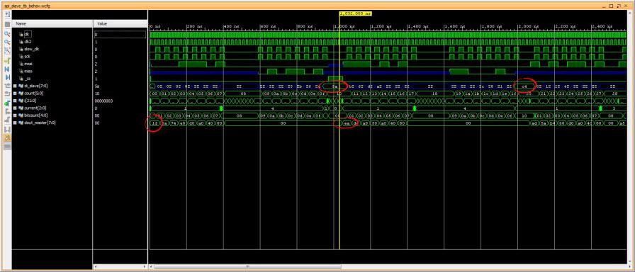
Waveform of the simulated SPI slave device.
Looks like it will work, so my next step is to create the custom IP package for it.
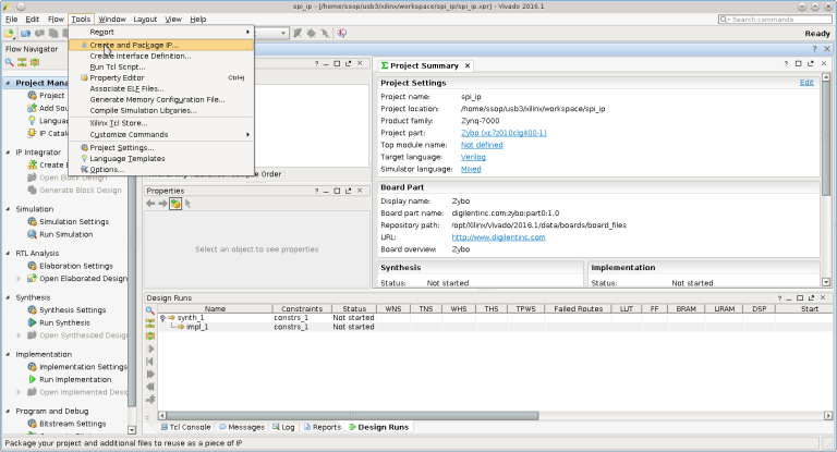
Create and package IP
Start vivado and do these steps to create the custom IP that will be integrated into the design later,
. Quick Start -> Create new project -> next
. Fill in the Project name and project location. Project name set to spi_ip and project location set to my local workspace -> next.
. Project type leave it as RTL project -> next.
. Add existing IP -> next since no existing IP to be added in this page.
. Add constraints -> next since no constraint to be added in this page.
. Default part -> Boards -> Zybo ->next (select Zybo).
. New Project Summary -> Finish.
. Tools -> Create and package IP -> next -> Create a new AXI4 peripheral.
. Peripheral Detail -> name set to myspi_ip -> next.
. Add interface -> next
. Create Peripheral -> Edit IP -> Finish.
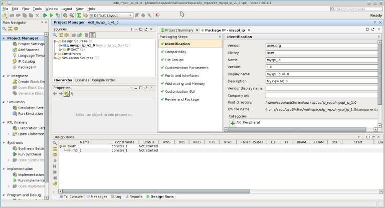
After edit_myspi_ip_v1_0 pops up, add spi_slave.v and modify the AXI template as necessary,
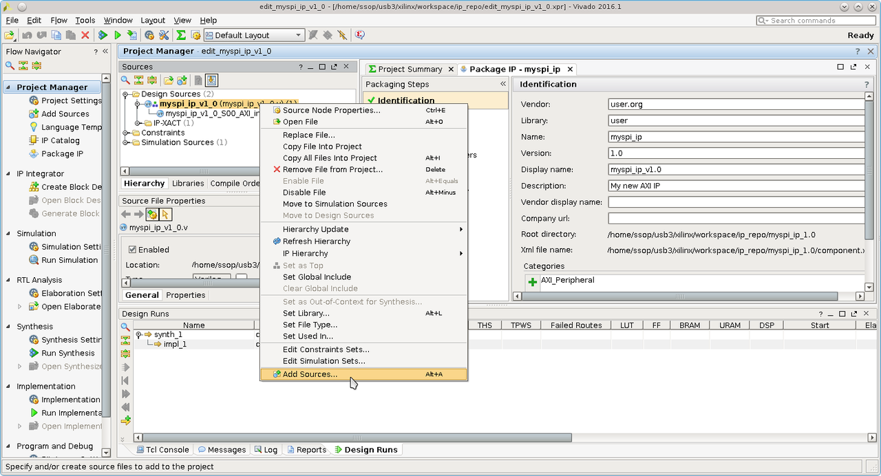
. Under Design Sources, right click on myspi_ip_v1_0 and select add sources to add spi_slave.v.
. Double clicks on myspi_ip_v1_0.v to open for editing.
. Add the following code,
// Users to add ports here
input wire spi_cs,
input wire spi_mosi, //it is input with respect to this slave
input wire spi_sck,
output wire spi_miso,
// User ports ends
. Save and close myspi_ip_v1_0.v file.
. Double clicks to open myspi_ip_v1_0_S00_AXI.v for editing. Add the following code to instantiate the custom SPI slave IP,
    // Users to add ports here
    input wire _cs,
    input wire mosi,
    input wire sck,
    output wire miso,
    // User ports ends

    ..
    //instantiate spi_slave here at the end of the file.
    // Add user logic here
spi_slave myspi(
._cs(_cs),
.miso(miso),
.mosi(mosi),
.sck(sck),
.clk(S_AXI_ACLK));
    // User logic ends
. Save and close the source file, myspi_ip_v1_0_S00_AXI.v.
. File Groups -> Merge change Groups Wizards to merge all the changes made.
. Review and Package -> Re-package IP.
. Finised packaging. Do you want to close the project -> yes.
. Close spi_ip project.
This completed packaging the SPI slave IP for this demo. The IP is packaged and stored in the ip_repo in my local workspace (default).
Create Zynq design block with the custom SPI slave IP
Having custom IP ready, now it can be integrated into the Zynq Zybo system. Starting a new project,
. Quick Start -> Create a New Vivado Project -> next.
. Project name set to zybo_spi and project location set to local workspace then -> next.
. Project Type set to RTL project -> next.
. Add sources -> next (no source to add).
. Add existing IP -> next.
. Add constraints -> next.
. Default part -> Boards -> zybo -> next.
. New Project Sumamry -> Finish.
Create zynq block design,
. Flow Navigator -> IP Integrator -> Create Block Design.
. Design Name set to zybo_spi -> Ok.
. Diagram -> Add IP to add Zynq.
. Double click Zynq7 processing syatem to add ZYnq block. This is the PS. PL (IP) is to added next.
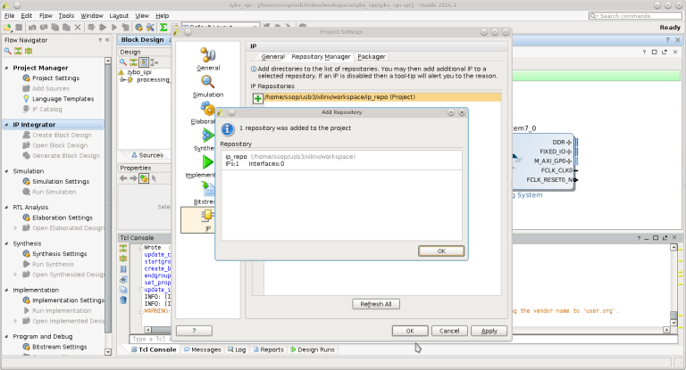
. Project Manager -> Project Settings -> IP -> Repository Manager. Click (+) to add IP repository where spi_ip is packaged. Click Ok when done.
. Diagram -> Add IP. Type myspi in search box of IP list and select myspi_ip_v1_0 to add.
. Diagram -> Run block automation and Run Connection automation for Zynq and SPI slave IP -> Ok.
. Edit Zynq7 PS from default design before making the connections,
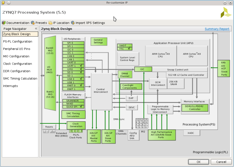
. Double click on Zynq7 PS in the block diagram to open its setting (Zybo default).
. Recustomize IP -> MIO Configurations -> SPI0 click to enable and leave it at EMIO interface -> OK.
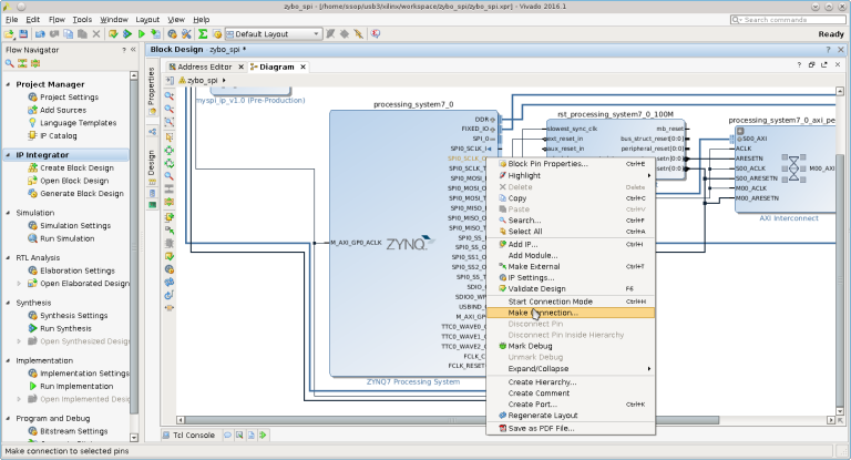
. Now SPI0 appears in Zynq7 block. Expand it to make connection to SPI slave IP.
. Make connections between Zynq7 to myspi_ip_0 block: SPI0_MOSI_O->spi_mosi, SPI0_MISO_I->spi_miso, SPI0_SCLK_O->spi_sck, SPI0_SS_O->spi_cs.
. Diagram -> Validate Design.
. Design sources -> Zybo_spi.bd -> Create HDL Wrapper, Let Vivado manage wrapper and auto-update -> OK.
. IP Integrator -> Generate Block Design -> Generate.
. Flow Navigator -> Run Synthesis.
. Run Implementation.
. Generate bitstream.
. Skip Open Implemeted Design. Click Cancel.
. File -> Export -> Export Hardware (include bitstream ).
. File -> Launch SDK -> OK.
The bitstream generated for this design is zybo_spi_wrapper.bit. This will be used later.
Generating device tree
Next step is to generate device tree for the BSP of this design. On Xilinx SDK,
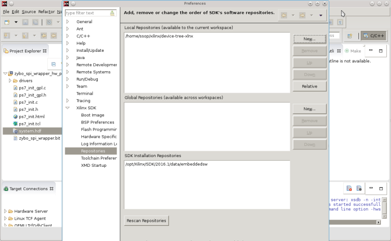
. Xilinx Tool -> Repositories, add device-tree-xlnx for local workspace.
. File -> New -> Board Support Package. Board Support Package OS set to device_tree -> Finish.
. View the generated file in device_tree_bsp_0. Files of interest are zynq-7000.dtsi and system.dts.
. File -> Exit to close SDK.
Device tree files are store in my workspace/zybo_spi/zybo_spi.sdk/device_tree_bsp_0 directory. The device-tree-xlnx is pulled from Xilinx github (https://github.com/Xilinx/device-tree-xlnx).
Port device tree to Linux kernel
There are two files that need to be replaced or modified, zynq-7000.dtsi and zynq-zybo.dts. Both of these are located in linux-xlnx/arch/arm/boot/dts directory which is Xilinx's kernel git version. I replace the original zynq-7000.dtsi with the one generated from my design and add portion of code in system.dts into the existing zynq-zybo.dts as follows,
//add this custom spi0 block for my custom driver, spi5a
&spi0 {
        is-decoded-cs = <0>;
        num-cs = <3>;
        status = "okay";

        spi5a@0 {
        compatible = "souk,spi5a";
        reg = <0>;
        spi-max-frequency = <1000000>;
      };

};//end of zynq-zybo.dts
Since my Zybo's kernel(zImage) has already been compiled, I only need to recompile the device tree.
make ARCH=arm CROSS_COMPILE=arm-linux- zynq-zybo.dtb
follow by appending the device tree blob to zImage for booting. This is creating the U-Boot FIT image,
mkimage -f kernel.its zImage.itb
The kernel.its is the FIT image description source file. This file is created and placed in linux-xlnx/arch/arm/boot/ directory. I 'cd' to this directory to create the FIT image. This is the content of kernel.its,
 /dts-v1/;

/ {
         description = "ARM Zynq Zybo FIT (Flattened Image Tree)";
         #address-cells = <1>;

         images {
                 kernel@1 {
                         description = "ARM Xilinx Zynq Linux-4.x";
                         data = /incbin/("zImage");
                         type = "kernel";
                         arch = "arm";
                         os = "linux";
                         compression = "none";
                         load = <0x800000>;
                         entry = <0x800000>;
                         hash@1 {
                                 algo = "crc32";
                         };
                         hash@2 {
                                 algo = "sha1";
                         };
                 };

                 fdt@1 {
                         description = "ARM Zynq Zybo device tree blob";
                         data = /incbin/("dts/zynq-zybo.dtb");
                         type = "flat_dt";
                         arch = "arm";
                         compression = "none";

                         hash@1 {
                                 algo = "crc32";
                         };
                         hash@2 {
                                 algo = "sha1";
                         };
                 };

         };

         configurations {
                 default = "config@1";

                 config@1 {
                         description = "Zynq Zybo";
                         kernel = "kernel@1";
                         fdt = "fdt@1";
                 };

                 };
 };
Custom Linux SPI slave device driver
The final step is to create the Linux SPI slave device driver. This should be very simple to create since it is for the do-nothing device. It is the driver that only exercises/validates the SPI protocol. As shown in the verilog code, this device only accepts three commands: READ_ID(0x1d) where it will return the value of 0x5a as its ID. READ(0xea) where it will return value *0xc4, and WRITE(0xad). WRITE command will not return anything. It is meant for this SPI slave device to act upon it. For this design it does not do anything with data written from host (master SPI). Here is major the code for SPI slave device driver, spi5a.c, which is very simple. All it does is reading ID and reading a fixed data from the SPI slave on loading. It is to prove that if the data return from these operations, then the SPI slave device works.
Line 7,8 setup kernel SPI device interface. Line 11,20 read SPI slave device and display the result. Next is to compile the device into kernel module to obtain spi5a.ko.
Test the SPI slave device
Next is to test the custom SPI device. For this, Zybo has to boot up to login prompt and bitstream has to be loaded follows by loading the driver.
. Boot up and login to Zybo. The kernel image is the version built with the generated device tree of this design having SPI0 enable for use. The Xilinx default version from git will not work for this design. This is the whole idea of everything that was done in prior steps.
. Load zybo_spi_wrapper.bit, load the Linux spi5a custom driver and observe the result. These two files are stored in my local root directory of rootfs.
|
# cat zybo_spi_slave_wrapper.bit > /dev/xdevcfg
|
|
# insmod ./spi5a.ko
|
|
spi read ID for cs 0, mode 0, bpw 8
|
|
spi5a_probe returns id= 0x5a
|
|
spi5a_probe read(ea) returns 0xc4
|
Line 1 is to load the generated FPGA bitstream (PL) of this simple hardware. Line 2 is to load the linux kernel module which is the SPI slave device driver. Line 3 is the debugging message to confirm the SPI device that the driver is communicated with.
I get the result I expected (line 4,5) , reading device ID returns 0x5a, and read return 0xc4. This is consistent to what being set in the synthesized Verilog code, spi_slave.v
Packaging bitstream to the system
Since I am using U-Boot and Linux OS for my Zybo board, I can automate the process of loading the bitstream at U-Boot stage by U-Boot script and U-Boot command. U-Boot for this board supports FPGA bitmask loading, using U-Boot's fpga loadb 0 $loadaddr $filesize (line 18) will load this bitstream as demonstate below,
Instead of tftp load as shown above. The FPGA bitstream file can be read from SD card and load to the Zynq in the same way following by the normal boot sequence ie.. loading kernel image. Once at Linux OS, loading bitstream via
#cat zybo_spi_wrapper_bit > /dev/xdevcfg
is no longer required. This is my preferred way of loading bitstream.
Conclusion
This concludes that PS-PL interface of the Zynq works for this design and it is coherent with respect to high level OS (Linux), that is the master SPI controller of the Zynq PS can communicate with the custom SPI slave of the PL with its standard SPI protocol. Although the design of SPI slave device in this exercise is a do-nothing, it merely exercises the PS-PL interconnectivity, I think it can be expanded to do some useful work.
Source code for this exercise is at https://github.com/souktha/zybo_spi_slave
Citations
- 1
-
Zybo(TM) FPGA Board Reference Manual, zybo_rm.pdf, Februrary 2013, Zybo rev B, Digilent.
- 2
-
Zynq-7000 All Programmable SoC Techincal Reference Manual, ug585-Zynq-7000-TRM.pdf, Feb 2015, Xilinx.
- 3
-
Zynq-7000 All Programmable SoC Embedded Design Tutorial, UG1165(v2015.3), ug1165-zynq-embedded-design-tutorial.pdf, Sept 30 2015, Xilinx.
- 4
-
Zybo FPGA Board Reference Manual, Revised Feb 2013, Rev B, Digilent Inc.