RS(n,k) code HDL implementation
This post is the implementation part of the my post on RS code workout where I did some math workout on the RS forward-error-correcting code (FEC). I find it to be simple enough to implement it in verilog that can eventually be synthesized for FPGA. I choose the simplest algorithm to implement the RS (15,9,7) as outlined in my last post.
Encoder
For Verilog, all of these coefficient multiplications can be a modeled by the simple modules that can be instantiated as the components of the RS encoder. The main part of this RS encoder with \(g_7(x)\) as its generator is listed below (minus the interface portion).
-
32-bit data input to be encoded.
. encoder_enable(1), enable encoder. This shall remain asserted while decoding is in progress.
-
24-bit output parity check
. bsy(1), decoder status. Asserts while encoder is processing data. Host wait for bsy to go low before inputting the new data.
. rdy(1), data ready. Asserts on data ready upon encoding completion.
. outw(24), 24-bit output parity check bits.
Host can then append the returned parity check bits to its 32-bit input data to form a complete coded word in systematic form. The actual data bit is 36-bit (9 symbols-bit), but shortened to 32-bit in this case.
Line 3 takes the shifted symbol input, modulo-sum with the output of b5. Its output, rtemp is then fed to the divider circuit.
Line 13-34 performs continuous multiplication of \(\alpha^i\) with rtemp and modulo-sum to each stage of the registers where they are connected as depicted in my workout post for this code. outcw contains the parity check bits where it can be concatenated to the input word to form a complete coded word.
An interface signal, rdy is then asserted on completion of encoding for each input word (interface circuit modeling not shown here).
Line 38-46 is the sample of one of the modules that compute \(\beta \alpha^9\).
The external interface part of this behavorial modeling is subjected to the implementation. The focus here is on algorithm to prove that it is mathematically correct and in agreement with the implementation.
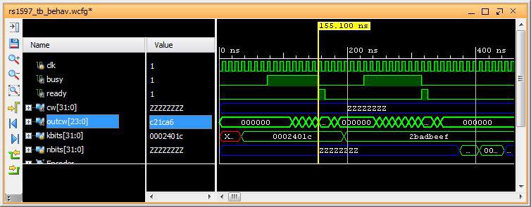
Fig1: The 24-bit parity check (c21ca6) for the encoded input word (2401c).
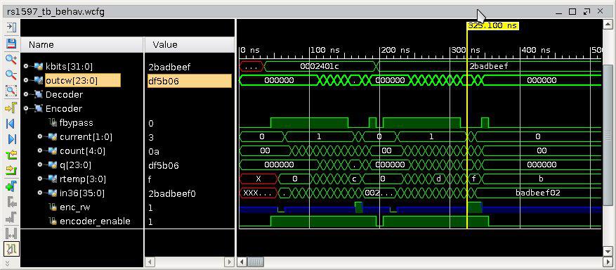
Fig1: The 24-bit parity check (df5b06) for the encoded input word (2badbeef).
Decoder and Error-Correction
The decoder takes in two 32-bit data, one is the message and one is the parity check data. The parity check data is 24-bit data (6 symbols of 4-tuple). In this implementation, the data will enter the decoder as h0002_401c and hC21C_A600.
To be able to correct any error is to first detect if there is any error. The error detection process is simply determined right after the input symbols(15) have been shifted into the decoder. The decoder is the same block as used for encoding with minor interface adjustment. Basically it is the same module \(g_7(x)\) as worked out in my other post. Simple interface,
-
32-bit data input to be encoded.
. rw(1), host writes one 32-bit data at a time for data and parity. Host writes sequence of two 32-bit data on deassertion of bsy. Host read data when rdy is asserted. If undecodable code, err is asserted.
. bsy(1) asserts while decoding in in progress and deasserts on completion.
. rdy(1) asserts when data is ready.
. decoder_enable(1), enable decoder. This shall remain asserted while decoding is in progress.
. data(31) input/output data.
-
32-bit data output.
. date(32) input/output data. Output data from decoder when bsy is deasserted and rdy is asserted.
. rw(1) read data when rdy is asserted.
Here is some example of its error correction,
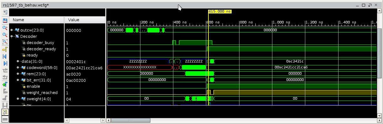
Fig1: Corrected 3 symbols(12-bit) of input coded word h0AC2_421C to h2_401C.
It can also correct burst error,
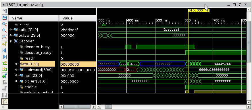
Fig1: Corrected zero code word with burst error of length 12.
Summary
The encoding/decoding that I implement is relatively simple, may be 200-300 lines of verilog code with the majority of it is for host interface. The algorighm itself is small for this exercise. So far it can correct error any where whether the error is in message portion or in parity check portion. While my implementation may not be perfect, I think it is as simple as I can make.