Simple Cyclic Hamming (15,11,3) FEC

This post is the implementation part of the my post on simple cyclic Hamming code where I did some math workout on this type of forward error-correction code (FEC). I am doing it for fun since I think it is simple enough to implement it in FPGA. The generator for this exercise is \(g(x)=1+x+x4\) for an \((n,k,d) \equiv (15,11,3)\) code.

Implementation

If the data to be encoded is parallel data block, the encoded message can simply be done with simple combinational logic based on the \(G\) matrix, likewise for the decoder logic, but this is too boring. I choose to complicate this matter by assuming that the input data bits to be encoded or decoded arrive serially, perhaps from a transceiver part of the circuit. This way I can implement it with divider circuit and get myself frustrated with timing closure and everything else. Simple and elegant way is not always paid off. This is what I am going to do.

For this exercise, I am targeting the Xilinx Artix FPGA device. I create three verilog modules,

. Encoder for encoding 11-bit message to 15-bit message.

. Decoder for decoding the 15-bit receiving message.

. Corrector is for correcting the error if syndrome indicates the error.

The encoder

The encoder takes a stream of 11-bit input message and encodes it to 15-bit messages in systematic form. The input bit is clocked in bit-by-bit to the encoder whenever enc_enable is asserted. On the completion of the encoding process, the rdy is asserted as an output ready indicator so that the 15-bit encoded message can be read.

     /*(n,k,d) = (15,11,3)
     input is serialized 11 bits, output is 15 bits*/
     module cyclic_1_x_x4_encode #(parameter IWIDTH=11, OWIDTH=15) (
         input clk,
         input enc_enable, //enable encoder
         output bsy, // state of encoder
         output rdy, // 1 when decoded data is ready for reading.
         input  ibit, //serialize input bit input code word
         output [OWIDTH-1:0] codeword
         );
         ..
         ..
         assign fbypass = (count <= `KBITS);
         always@(posedge clk ) begin
             if ( enc_enable ) begin
                 if ( count == 5'h0  ) begin
                     busy <= #1 1'b0;
                     ready <= #1 1'b0;
                 end
                 else begin
                     if ( fbypass  ) begin
                        /*pass through k bits of message*/
                         busy <= #1 1'b1;
                         ready <= #1 1'b0;
                         cw <= {cw[OWIDTH-2:0],ibit}; //left shift to MSB begin with 1st bit
                         end
                     else begin
                         cw <= {cw[OWIDTH-2:0],q[3]}; //concat parity bits to form coded word
                         if (count >= `NBITS) begin
                          busy <= #1 1'b0;
                          ready <= #1 1'b1;
                         end
                         end
                 end
             end
             else begin
                 cw <= 15'h0;
                 busy <= #1 1'b0;
                 ready <= #1 1'b0;
                 end
         end
         /*encoder for generator g(x) = 1 + x + x**4*/
         always@(posedge clk) begin
             if (enc_enable) begin
                 q[3] <=  q[2];
                 q[2] <=  q[1];
                 if ( fbypass )  begin
                     q[1] <=  q[3] ^ q[0] ^ ibit;
                     q[0] <=  ibit ^ q[3];
                 end
                 else begin
                     q[1] <= q[0];
                     q[0] <= 1'b0;
                     end
                 if ( count == 5'h0 )
                     q <= 4'b0000;
             end
             else
                 q <= 4'b0000;
         end
     endmodule

Th encoder part of this module is between line 16-46. The divider circuit that forms the \(P_i\) bits is between line 49-67. The lines that forms the output coded word are at line 29 and 32. The sample simulation below shows one of the encoded message. Any \(2^{11}\) input message words can be encoded by this circuit and matches with the multiplication of the \(G\) matrix. This is how I know that the divider circuit works.

../../images/hardware/encode_h1.jpg

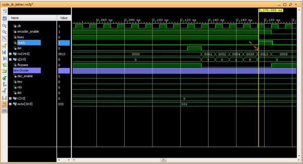
Fig1: encoded message 01h

The decoder and FEC

The FEC decoder is the reverse of the encoder where it takes in the serial 15-bit code word, computes the syndrome and if any 1-bit error is detected, the instantiated lookup bit correction will return the correctable bit position. This completed the FEC process.

     module cyclic_1_x_x4_decode #(parameter IWIDTH=15, OWIDTH=11) (
         input clk,
         input dec_enable, //enable decoder
         input  ibit, //serialize input bit input code word
         output bsy, // state of decoder
         output rdy, // 1 when decoded data is ready for reading.
             output err, // error if undecodable
         output [OWIDTH-1:0] outw //11 bit output decoded word
     );
     ..
     ..
     assign outw = cw[IWIDTH-1:`PBITS] ^ bit_correction[IWIDTH-1:`PBITS]; //bit 4 to 14 for this case
     always@(posedge clk ) begin
             if (dec_enable ) begin
                     if ( count == 5'h0 ) begin
                             busy <= #1 1'b0;
                             ready <= #1 1'b0;
                     end
                     else begin
                             if (count < `NBITS) begin
                                     /*This is to output data long enough to be read.*/
                                     busy <= #1 1'b1;
                                     ready <= #1 1'b0;
                                     end
                             else begin
                                     busy <= #1 1'b0;
                                     ready <= #1 1'b1;
                                     end
                             quotient <= #1 {quotient[IWIDTH-2:0],r[3]}; //shift in MSB
                     end
             end
             else begin
                 busy <= #1 1'b0;
                 ready <= #1 1'b0;
             end
         end
/*dvivider for g(x) = 1 + x + x**4*/
always@(posedge clk) begin
     if (dec_enable ) begin
             if ( count == 5'h0 ) begin
                 r <= 4'b0000;
                 ierr <= 1'b0;
             end
             else if ( count <= `NBITS ) begin
                     r[3] <= r[2];
                     r[2] <= r[1];
                     r[1] <= r[3] ^ r[0];
                     r[0] <= ibit ^ r[3];
                     cw <= {cw[IWIDTH-2:0],ibit};
                     if (r != 4'h0 ) begin
                             ierr <= 1'b1;
                     end
             end
             end
             else begin
                 r <= 4'h0;
                 ierr <= 1'b0;
             end
end
assign lookup_en = ierr;
lookup11 correct(
     .en(lookup_en),
     .syndrome(r), //the remainder of division
     .errbits(bit_correction)
     );
endmodule

The divider circuit (line 44-65) for the decoder is similar to that of the encoder, but it performs syndrome computation by taking all the input bits having the remainder shifted into the decoded output word. If the remainder is non-zero, it set ierr bit as an enabler for lookup11 module (line 67-73). The table lookup module returns the corresponding bit error, bit_correction, where it does the modulo-2 sum to the decoded word (line 16). This is the FEC.

The lookup module is a simple ROM type lookup table using the 4-bit syndrome as the index to the correction bit. It returns non-zeros for errbits on any error, zeros otherwise. It covers both message bits and parity bits.

     module lookup11 #(parameter WIDTH=15) (
         input en,
         input [3:0] syndrome,
         output [WIDTH-1:0] errbits
         );
         reg [WIDTH-1:0] bitpos;
         assign errbits = bitpos;
         always@(*) begin
             if (!en) bitpos = 15'h0;
         else
         case (syndrome)
             4'h0: bitpos = 15'h0;
             4'h1: bitpos = 15'h1;
             4'h2: bitpos = 15'h2;
             4'h4: bitpos = 15'h4;
             4'h8: bitpos = 15'h8;
             4'h3: bitpos = 15'h10;
             4'h6: bitpos = 15'h20;
             4'hc: bitpos = 15'h40;
             4'hb: bitpos = 15'h80;
             4'h5: bitpos = 15'h100;
             4'ha: bitpos = 15'h200;
             4'h7: bitpos = 15'h400;
             4'he: bitpos = 15'h800;
             4'hf: bitpos = 15'h1000;
             4'hd: bitpos = 15'h2000;
             4'h9: bitpos = 15'h4000;
         endcase
         end
     endmodule
../../images/hardware/decode_73d.jpg

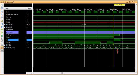
Fig1: decoded non-error message 0x73d for 0x73

I test the FEC logic with random test vector for several coded words out of \(2^{11}\) possible coded words and I can verify that any single bit error is corrected as it is a \(t=1\) FEC. The code rate for this implentation is \(\frac{k}{n} = \frac{11}{15}\)

What is really needed for this FEC is only to correct the message error bit, any bit of the 11-bit. The err bit can be used as a request for retransmission if the error bit falls into the parity area. This means that certain syndrome in the look up table will be partially used.

Shortened code \((n-l,k-l,d)=(12,8,3)\) can also be obtained using this exact scheme with minimal change to the logic because it is more practical to do it in 8-bit rather than 11-bit. It is no longer cyclic, but it offers the same error-correcting capability as its normal version.

../../images/hardware/decoded_33d.jpg

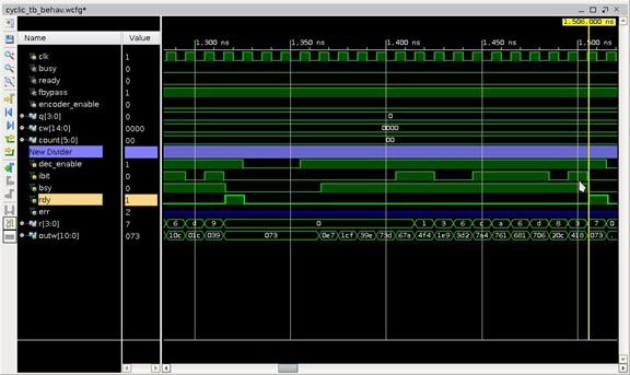
Fig1: FEC 1-bit error (bit 6) in coded word. Decoded and Corrected 0x33d for 0x73

I believe that my implementation is what is called Meggitt decoder. Since I do not take into account the error confinement, it has certain restriction such as error trapping so future improvement is needed.

Conclusion

Cyclic code FEC of this type can be easily implemented with shift registers to perform modulo division. The FEC in this exercise may not be efficient, but if it requires that the FEC be implemented with minimal gates then it would be practical.

When time permits, I will try to implement \(t > 1\) FEC.