Implementing BCH (15,7,5) FEC
This post is the implementation part of the my post on Binary BCH (15,7,5) workout where I did some math workout on the BCH forward-error-correcting code (FEC). I find it to be simple enough to implement it in verilog that can eventually be synthesized for FPGA. I choose the simplest algorithm for decoding the binary BCH (15,7,5) as outlined in my last post.
Implementation
The implementation can be targeted to any FPGA device. Since I am usinx Xilinx Vivado, I am targeting it for Zynq or Artix type of device. For now, I am focusing on getting the main algorithm to work correctly. The implementation is less then 300 lines of code which I think it is fairly simple and straight forward. I implement it as a serialized transceiver model. The simple specification of the top module, bch15_7_5_decode,
-
Input (n bits):
. dec_enable(1), enable decoder. This shall remain asserted while decoding is in progress. Host shall deassert this signal upon detecting deassertion of bsy.
. ibit(1), serialized input bit (MSB first). Host shall wait for deassertion of bsy prior to placing data on ibit as data will be strobed on the rising clock.
-
Output (n bits)
. bsy(1), decoder status. Assert by decoder while processing data. Host shall wait for bsy to go low before asserting dec_enable. If dec_enable is deasserted, bys is automatically deasserted. This signal is deasserted on completion of decoding.
. rdy(1), data ready. Assert on data ready upon decoding completion.
. err(1), error status. Assert on uncorrectable error.
. outw(7), 7bit decoded code word.
Decoder decodes 15 bits coded word input to 7 bits output with 2 bits error forward-error correcting capability. For parallel input data bits, simply change input ibit to input [IWIDTH-1:0] ibit, and change the inputting scheme of module_gx. The parallel data case saves half the number of bit shiftings. This will make it roughly twice as fast.
Decoding algorithm
1 Calculate syndrome \(s(x) = w(x)\ mod\ g(x)\) from the received codeword \(w(x)\).
2 For \(i \ge 0\), calculate \(s_i(x)=x^i s(x)\ mod\ g(x)\) until \(s_j(x)\) is found where weight of \(s_j(x) \le t\).
3 Once \(s_j(x)\) is located, \(e(x)=x^{n-j}s_j(x)\ mod\ (x^n + 1)\) are the most likely error bits.
The iteration for this one is at most \(2t\) because if there are \(\nu \le t\) error positions, the iteration is \(\nu + t\).
The generator for this implementation is,
The decoder and FEC
The BCH FEC decoder takes in the serial 15-bit code word (MSB first), detects if there is any error in the input codeword, and computes the most likely bit(s) error position. The corrected codeword is returned as its 7-bit output word.
The top module, bch15_7_5_decode, instantiates two submodules, module_gx and compute_error_cw.
The submodule, modulo_gx performs syndrome computation continuously while input data is being shifted into its divider circuit and it also output the computer code's weight from the result. This is step 2 of the algorithm. If \(weight \le 2\) and all the input bits are in, the circuit then enable the bits error computation circuit. This is step 3 of the algorithm.
step 3 of the algorithm performs final bit(s) error computation based on the result from modulo_gx module. This module takes the syndrome, \(s_j(x)\), shift-multiplies by \(x^{15-j}\) then takes the modulo \((1+x^{15})\). The resulted bit(s) error needed for correction is err_bits where it is added to the input code word. The correction bits error includes both the information bits and the parity bits. The final FEC code word is the upper 7 bits of the corrected code word.
Some sample of waveforms captured from the test bench based on this algorithm is shown for various situation of bit(s) error. The simulation is for 100MHZ FPGA clock.
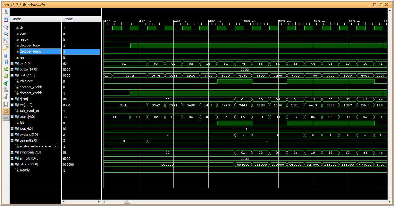
Fig1: 15bit code word 0x033e with 2 bits error (expect 0x63)
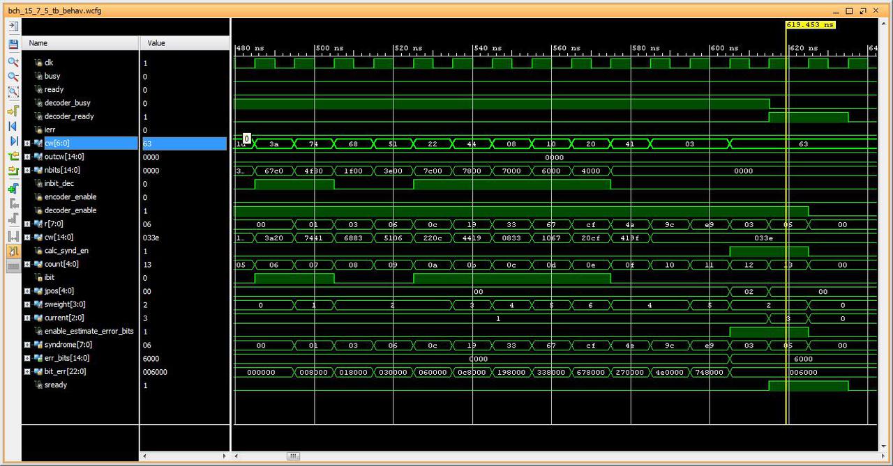
Fig2: Coded word 0x033e with 2 bits error corrected. Output 7bit word is 0x63
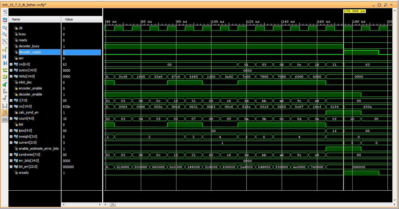
Fig3: Non-error codeword, decoded as-is (0x63).
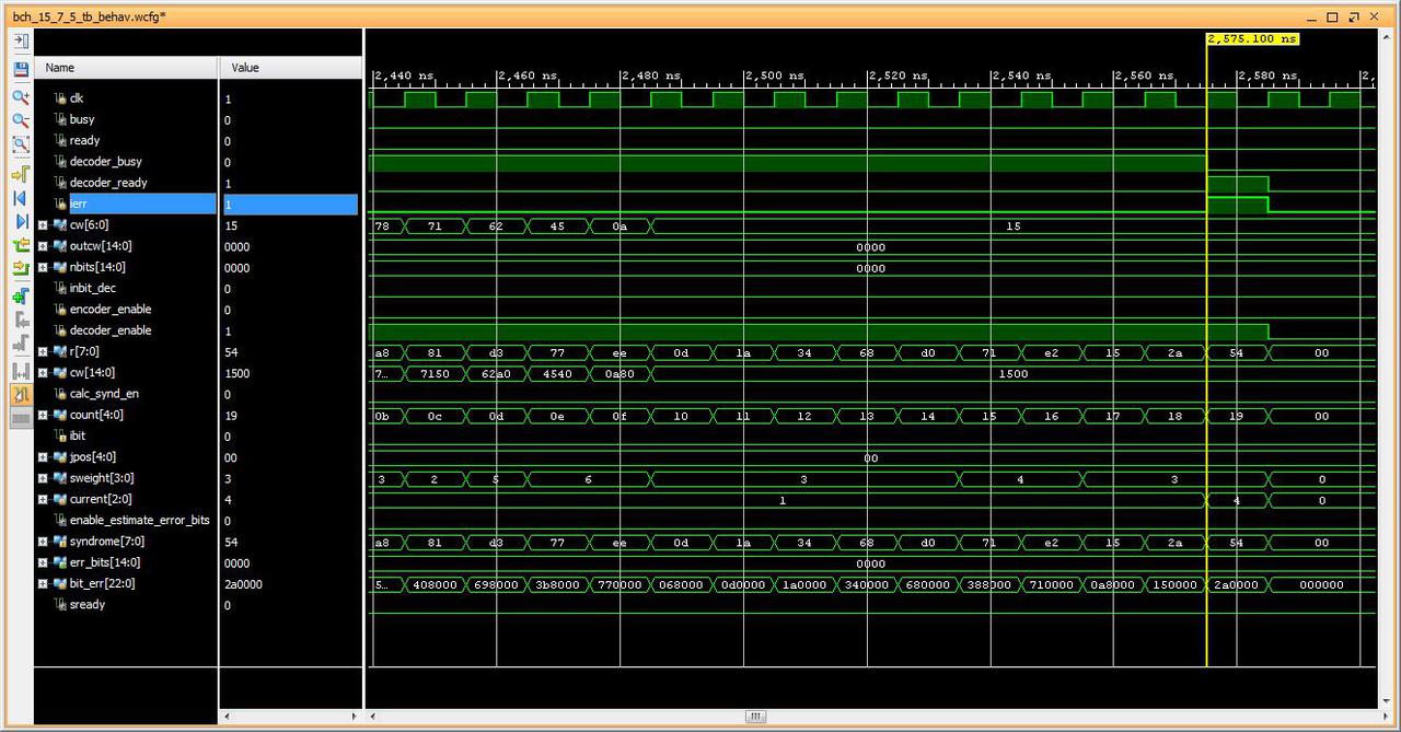
Fig3: Non-correctable code word, code word 0x00 (0x1500) with 3 bits error. Decoded as error.
It takes only one clock to decode the non-error code word, immediately after the last input bit is shifted, and a maximum of four clocks for returning the corrected code word for the case where two or less error bits to be corrected. It takes eight clocks to declare the non-correctable error.
Conclusion
It appears that the algorithm works, at least as simulated. It is a proof of concept. If the math is right, so will be the circuit since math is everything and everything is math. Timing analysis and adjustment may be necessary on synthesis, but I will leave it for next time.